8 August 2012

HOW TO WORK ON KEIL SOFTWARE ...STEP BY STEP GUIDE OF KEIL SOFTWARE WORKING MANUAL WITH SCREEN SHOT


STEP BY STEP GUIDE OF KEIL SOFTWARE WORKING MANUAL WITH SCREEN SHOT 
The steps or following
1.Click on the Keil u Vision Icon on Desktop.
2.Click on the Project menu from the title bar
3.Then Click on New Project


4.Save the Project by typing suitable project name with no extension in u r own folder sited in either C:\ or D:\


5.Then Click on Save button above.
6.Select the component for u r project. i.e. Atmel……
7.Click on the + Symbol beside of Atmel


8.Select AT89C51 as shown below


9.Then Click on “OK”
The Following fig will appear


10.Then Click either YES  or NO………mostly “NO”


Now your project is ready to USE
11.Now double click on the Target1, you would get another option “Source group 1” as shown in next page.
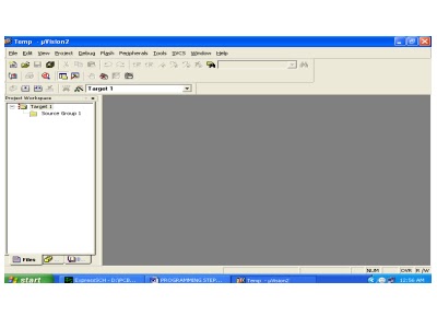


12.Click on the file option from menu bar and select “new”


13.The next screen will be as shown in next page, and just maximize it by double clicking on its blue boarder.


14.Now start writing program in either in “C”  or “ASM”
For a program written in Assembly, then save it with extension “. asm”  and  for “C” based program save it with extension “ .C”


15.Now right click on Source group 1 and click on “Add files to Group Source”


Now you will get another window, on which by default “C” files will appear.


16.Now select as per your file extension given while saving the file
Click only one time on option “ADD”
Now Press function key F7 to compile. Any error will appear if so happen.
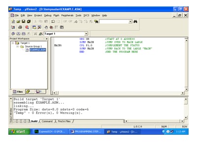


18.If the file contains no error, then press Control+F5 simultaneously.
The new window is as follows


19.Then Click “OK”

Now Click on the Peripherals from menu bar, and check your required port as shown in fig below


20.Drag the port a side and click in the program file.


21.Now keep Pressing function key “F11” slowly and observe.
You are running your program successfully

Click here to see the video tutorial  of  KEIL From Youtube

http://www.youtube.com/watch?v=g_UlJlyD4Kk


8 July 2012

Temperature indicator by using microcontroller At89c52


Here’s a micro controller-based temperature indicator that displays the temperature in the range of –55°C to 125°C. Besides AT89C52 micro controller, it uses a temperature sensor chip and an
LCD module. The indicator outputs the calibrated data in digital form. The program
for the micro controller is written in C and not in Assembly language. Since C program
has well-defined syntax, it far outweighs the merits of the Assembly
language program. shows the block diagram of the temperature indicator using micro controller
AT89C52. The power supply for the circuit is regulated by IC 7805 and supplied to different parts of the unit. DS1621 is the temperature sensor chip. The micro controller unit (MCU) reads
the temperature from the sensor. The temperature data is compared with certain user-defined temperature values and processed inside the MCU as per the program and then sent to the LCD for display. shows the circuit of temperature indicator using micro controller AT89C52. Working of each section of the circuit is covered in the following paragraphs

Temperature sensor.
 Temperature sensor chip DS1621 (IC3) is an 8-pin DIP IC. Its pin details are shown in Fig. 3 and the internal block diagram in Fig. 4. The chip can measure temperatures from –55°C to +125°C in 0.5°C increments, which are read as 9-bit values. It can operate off 2.7V to 5.5V. Data is read/written via a 2-wire serial interface. Pins 1 and 2 of the temperature
IC are connected to pins 11 and 10 of the micro controller, respectively. The thermal below user-defined low temperature TL. User-defined temperature settings are stored in the non-volatile memory. Temperature settings and temperature readings are all communicated to/from IC DS1621 over a 2-wire serial cable. The most significant bit (MSB) of the data is transmitted
first and the last significant bit (LSB) is transmitted last.
here’s a micro controller-based temperature indicator that displays the temperature in the range of –55°C to 125°C. Besides AT89C52 micro controller, it uses a temperature sensor chip and an
LCD module. The indicator outputs the calibrated data in digital form. The program
for the micro controller is written in C and not in Assembly language. Since C program
has well-defined syntax, it far outweighs the merits of the Assembly
language program. shows the block diagram of the temperature indicator using micro controller
AT89C52. The power supply for the circuit is regulated by IC 7805 and supplied to different parts of the unit. DS1621 is the temperature sensor chip. The micro controller unit (MCU) reads
the temperature from the sensor. The temperature data is compared with certain user-defined temperature values and processed inside the MCU as per the program and then sent to the LCD for display. shows the circuit of temperature indicator using micro controller AT89C52. Working of each section of the circuit is covered in the following paragraphs

Power supply.
 The power supply unit consists of a step-down transformer (230V AC primary to 0-9V, 250mA secondary), bridge rectifier and voltage regulator. The output of the transformer is fed to bridge rectifier diodes D1 through D4 (each 1N4007). The ripple from the output bridge
rectifier is filtered by capacitor C1 and fed to regulator IC 7805. The regulated output is given to the temperature sensor, micro controller unit and LCD module, respectively. When switch S1 is closed, LED1 glows to indicate the presence of power in the system..

note : it was a project idea and you have to develope your own code.and if you can not develope then you can reques the code in comments.
You can sea many microcontroller tutoriols at mytutorialcafe .com
Related Posts Plugin for WordPress, Blogger...